Geometric Dimensioning and Tolerancing Solutions for Manufacturing & Inspection
Misapplied tolerance callouts create rework, scrapped parts, and production delays. Our geometric dimensioning and tolerancing solutions give manufacturers, engineers, and quality teams the GD&T analysis and print review needed to prevent them.
At 3D Engineering Solutions, we apply GD&T best practices and formal tolerance stacking analysis to identify design risks, correct print inconsistencies, and support compliant, manufacturable designs across dimensional analysis, tolerancing quality control, and print review. Our work is backed by ISO/IEC 17025 accreditation and a staff of degreed, GD&T-certified engineers available for mechanical design engineering services across the full product lifecycle.
Geometric Dimensioning and Tolerancing Solutions for Communicating Design Intent
Geometric Dimensioning and Tolerancing is a symbolic language used on engineering drawings to communicate design intent and control how parts are manufactured and inspected. The system uses standardized symbols and feature control frames to define tolerances more precisely than traditional plus/minus dimensioning, with datum reference frames establishing the coordinate system for measurements and material condition modifiers like Maximum Material Condition (MMC) defining how tolerances are applied. For a full reference, see ASME Y14.5-2018, the governing standard for dimensioning and tolerancing in U.S. engineering practice.
Our certified engineers apply GD&T principles during inspection services, First Article Inspections, and reverse engineering projects. We interpret these symbols and callouts so measurements align with design intent whether we’re validating new tooling or documenting legacy parts.
Understanding GD&T Elements in Practice
GD&T operates through several interconnected concepts that work together to define part requirements clearly. Understanding these elements is necessary for accurate inspection and measurement work.
- Datum Reference Frame: Establishes the coordinate system (points, axes, or planes) used as the foundation for all measurements
- Feature Control Frame: The rectangular symbol that specifies the geometric tolerance, including the tolerance value and applicable datums
- Material Condition Modifiers: Symbols like Maximum Material Condition (MMC) that define when and how tolerances apply based on the actual size of features
- Basic Dimensions: Theoretical exact values that locate features but have no tolerance themselves
- Datum Features: Physical features on the part used to establish the datum reference frame
During our inspection and reverse engineering work, we apply these GD&T principles to ensure measurements reflect the design engineer’s intent. Whether we’re performing First Article Inspections or creating CAD models from existing parts, proper interpretation of these concepts helps us deliver accurate, reliable results that support successful manufacturing processes.
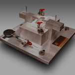
For precision inspection gauge and fixture solutions that are correctly built around your datum reference frames and GD&T controls, our design team works directly from your print requirements.
Geometric Dimensioning and Tolerancing Solutions That Prevent Production Errors
Geometric Dimensioning and Tolerancing errors can cost manufacturers thousands of dollars in rework, scrapped parts, and production delays. When GD&T callouts are misinterpreted or incorrectly applied, parts that should function properly may fail to assemble, creating cascading problems throughout the production process.
Common costly GD&T problems include:
- Tooling Modifications: We’ve seen suppliers forced into endless loops of tooling changes because tolerance conflicts weren’t identified until First Article Inspection
- Assembly Failures: Parts that measure correctly individually but don’t function as intended when assembled due to misunderstood datum reference frames
- Production Delays: GD&T errors discovered during production halt manufacturing while engineers resolve tolerance issues
Our tolerance stacking analysis identifies these conflicts before tooling begins. With 30 years of quality-assurance management experience, our certified engineers have seen how small GD&T errors carry major downstream consequences. We apply that knowledge whether we’re reviewing prints, performing First Article Inspections, or documenting reverse-engineered parts.
Applying GD&T Best Practices in Manufacturing
Proper application of GD&T requires understanding how tolerances interact with manufacturing processes and measurement capabilities. At 3D Engineering Solutions, we apply these guidelines during our inspection and reverse engineering services to ensure parts meet design intent.
- Measurement Uncertainty: The chosen inspection method must have adequate precision relative to the specified tolerance (we follow TUR ratios of ideally 10:1, acceptable down to 4:1)
- Material Condition Application: Understanding when Maximum Material Condition (MMC) or other modifiers apply affects the actual tolerance zone size
- Datum Hierarchy: The order of datums in the feature control frame directly impacts how the part is fixtured and measured
- Tolerance Stacking: Multiple GD&T callouts on related features must be analyzed together to prevent conflicts
Our certified engineers use these guidelines when reviewing prints for errors and inconsistencies. We can identify potential manufacturing or inspection issues early in the design phase and provide recommendations for tolerance adjustments that maintain design intent while supporting cost-effective production.
Where surface geometry adds complexity to your GD&T requirements, our team also provides complex freeform surface CAD development to support accurate modeling of Class A and Class B surfaces.
GD&T Symbol Categories and Applications
GD&T uses standardized symbols to communicate specific geometric requirements on engineering drawings. Our certified engineers interpret these symbols during inspection services to ensure measurements align with design intent.
Form
The form category controls the shape of individual features without reference to other features or datums. Straightness controls how straight a line element or axis must be within a specified tolerance zone. Flatness defines the tolerance zone within which a surface must lie, regardless of the part’s orientation. Circularity controls the roundness of circular elements across a cylinder, while cylindricity controls the cylindrical surface at one time.
Orientation
Orientation controls require features to maintain specific angular relationships to datum references. Perpendicularity requires a feature to be perpendicular to a specified datum within the stated tolerance. Parallelism controls how parallel a feature must be relative to a datum reference. Angularity specifies the allowable variation from a specified angle relative to a datum.
Location
Location controls define where features must be positioned relative to datums and other features. Position controls the location of features relative to datums and other features, commonly used with bolt hole patterns. Concentricity requires the axis of one feature to align with the axis of a datum feature. Symmetry controls how centered a feature is relative to a datum plane.
During First Article Inspections and reverse engineering projects, we measure these GD&T callouts using the appropriate datum reference frames. Our ISO 17025 certification ensures our measurements are traceable and reliable, whether we’re validating new tooling or documenting existing parts for reproduction.
GD&T Symbol Categories in Inspection and Manufacturing
| Category | Controls | Common Applications | How 3DES Applies It |
|---|---|---|---|
| Form | Shape of individual features (no datum reference required) | Flatness on mating surfaces, cylindricity on shafts, straightness on axes | Measured during CMM inspection and structured light scanning; reported per ASME Y14.5 |
| Orientation | Angular relationship of features to a datum | Perpendicularity on bores and pins, parallelism on mating faces, angularity on angled features | Applied during FAI and dimensional inspection using datum reference frames established from the print |
| Location | Position of features relative to datums and other features | True position on bolt hole patterns, concentricity on rotating assemblies | Measured with fixed CMMs and portable PCMMs; tolerance stacking analysis used to verify positional feasibility before tooling |
Get Expert GD&T Analysis for Your Next Project
Our ISO 17025 certified team can review your prints for inconsistencies, provide statistical tolerancing analysis, and deliver dimensional analysis results you can act on. From basic form controls to position tolerances on complex assemblies, we measure using the correct datum reference frames and document measurement uncertainty on every report. Our GD&T-certified engineers respond to most quote requests within one business day.
Precision, Experience, and Innovation: 3D Engineering
3D Engineering Solutions combines over 150 years of industry experience with advanced metrology technology, operating from a 24,000 square foot temperature-controlled facility in Cincinnati, Ohio. Our staff of degreed engineers includes NAS410 certified engineers, GD&T certified engineers, and specialists trained across all our measurement technologies. That depth means we understand not just how to collect data, but how to interpret it for your specific application, whether that involves troubleshooting, reverse engineering, First Article Inspection, or dimensional verification.
Our ISO/IEC 17025 certification, Federal Firearms and Explosives licenses, and ITAR registration allow us to serve clients across aeronautics, automotive, manufacturing, medical, and other precision industries, with 24/7 availability and same-day quotes on most projects.
Frequently Asked Questions
What are geometric dimensioning and tolerancing solutions?
Geometric dimensioning and tolerancing solutions involve applying GD&T principles, tolerance stacking analysis, and inspection methods to verify that parts will function as intended and can be manufactured within their specified requirements. At 3D Engineering Solutions, this includes print review, formal tolerance stacking, dimensional analysis, First Article Inspection, and manufacturing quality consulting for clients across aerospace, automotive, medical, and industrial sectors.
Why should I choose 3D Engineering Solutions?
We combine ISO/IEC 17025 certification with over 150 years of combined industry experience and state-of-the-art equipment. Our 24,000 square foot Cincinnati facility houses multiple technologies under one roof, allowing us to handle projects from individual parts to many thousands of parts scanning projects. We offer 24/7 service availability and typically turn quotes around within a day.
What services do you provide?
We offer 3D scanning services, industrial X-ray and CT scanning, reverse engineering, First Article Inspections (FAI), dimensional inspection, metrology services, and engineering project management. Our capabilities include laser scanning, structured light scanning, long-range laser scanning, photogrammetry, and industrial radiography with both contact and non-contact measurement methods.
What equipment do you have available?
We maintain multiple pieces of equipment for each scanning technology, including four Nikon X-ray/CT machines, industrial CT scanners, 7-axis articulating arms with laser capabilities, high-precision CMMs, large area gantry CMMs, surface finish equipment, structured light scanners, long range laser scanners, laser trackers and portable laser-based inspection equipment. Our digital x-ray systems include 160kV nano focus, 225kV microfocus, and 450kV microfocus units.
Every GD&T analysis and inspection report we deliver is backed by ISO/IEC 17025 accreditation and documented measurement uncertainty.