Common Contact Measurement Devices and Methods

Contact measurement devices constitute the majority of what is traditionally used for dimensional metrology. These consist of devices that must be in physical contact with the object to be measured. Below is a listing of general types of contact measurement devices. This covers the vast majority of what is used today and is a good overview on what is possible and what to expect from data taken with these instruments. We freely use these types of devices in our service business where it makes sense for any particular project due to quality, cost and timing.
One additional class of device that deserves mention as a traditional measurement device is the optical comparator. Since it is primarily a non-contact / touchless method it will be dealt with in this link on our article on Common Non-Contact Measurement Devices. But since these contact methods have for the most part been used over a long period time, it seemed right to give it a brief mention here as well.
Typical contact measurement tools include: Coordinate measuring machines (CMM), calipers, micrometers, depth micrometers, gage pins, gage blocks, height gages, surface plates, etc. Of those listed only the first one is a 3D measuring device. The others, typically, only measure 1 dimension. There are exceptions. One is the gage pin and maybe the gage block which can be used to measure the 3 dimensional aspect of a hole diameter (cylinder) and or a rectangular cut out slot. Another is the height gage that can be used to measure 2 dimensional circles and 3 dimensional cylinders in certain circumstances. The other devices, such as calipers, measure 2 opposing points that contact 3 dimensional objects but are only truly measuring in 1 dimension. Because of this, you have to be careful comparing caliper measurements to laser scan data as the caliper is measuring 2 distinct points at a time and the scanner is measuring potentially millions!
Hand tools
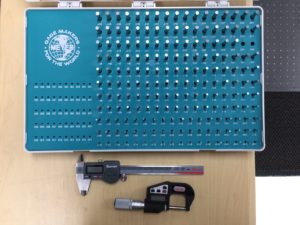
FIGURE 1: Some Common Hand Measurement Tools: Gage pin set, Calipers and Micrometers.
These 1 dimensional measurement devices (calipers, micrometers, gage pins, gage blocks, height gages) are more limited in what information you can obtain from them, but they are invaluable in their ease of use and speed of data extraction. They are also some of the most mis-used devices. Proper instruction on the use of each one of these devices will eliminate most of the issues found when using these for collecting data. Typical errors involve small amounts of dirt or debris that is on either the instrument or the object that interfere with accurate measurements, improper positioning of the instrument during inspection, not checking their calibration against a known standard (in the case of micrometers and calipers) and temperature effects from holding the instruments (pins, gage blocks) too long while measuring. However, in some cases these are the best devices to use for collecting a particular measurement.
In the example above, I mention using a gage pin to measure a hole. Since most holes are functional (you must be able to pass through an object of such and such size and not of another size) and these are very precise cylinders, you will get the best confirmation of hole size using gage pins. And because they are very well made cylinders (well ground and polished), their accuracy is far greater than most other equipment (millionths of an inch).
The accuracy of each of the various types of hand tools varies but generally ranges from the millionths to low thousandths of an inch.
We often mix in measurements from $2 gage pins or other hand tools with data from $1,000,000+ inspection equipment. Why? Because it is the right tool for the job. One of our advantages as a service provider is that we have a very wide range of measurement equipment and can apply the correct instruments for the job at hand. It is also really cool to have all of these nice tools (toys) in our tool box!
CMM
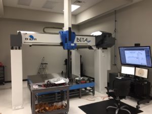
FIGURE 2: Gantry Fixed CMM
CMMs (coordinate measuring machines) come in a variety of sizes and are always more accurate and have lower measurement uncertainties associated with them than typical large point cloud scanning devices (non-contact instruments). They generally consist of 3 independent axis (XYZ) that use scales to indicate each of their positions relative to each other and the CMM. They have 2 general modes of operation: Single point and “scanning”. “Scanning” for a standard CMM refers to the practice of dragging a ball probe across the surface of the object being measured and continuously collecting points. This has the advantage of gathering a relatively large number of data points but has a lower associated accuracy than taking single points. For data collection on non-trivial parts (complex shapes), the amount of data becomes increasing critical. For example a CMM program that collects 10,000 points with a single point probing device is an extensive program. However if you were using “CMM scanning”, you could take many times more than that. Compare that to the touchless scanning technologies that would scan millions of points.
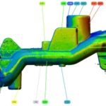
Many CMMs also have the advantage of being programmable and are typically used in most general inspection and FAI work. Manually operated CMMs (not CNC controlled) exist but are not as common. Because of their long history, everyone inherently believes the data from a CMM. They have been shown to be accurate over so many years and projects that most people do not even ask pertinent questions about the reports from them (is the unit in calibration for example). The data accuracy is great but you generally are just left with long sheets of blinding numbers. The numbers are specific and useful for judging dimensional acceptance, but are more difficult in being used for understanding trends across the piece being measured. So for most technically minded people, it is harder to pull out over arching trends within a single part. That may not be true for all people. However in my observation as an engineer for close to 30 years, it is the general rule. We tend to be visual and more likely to come to correct conclusions with surface color maps (typically seen with touchless scan data) than with reams of numbers. You can take the individual points you collect from a CMM and plot them against a corresponding CAD model (Scan to CAD). However, the general sparsity of the data still lends a lot to be desired for getting a good overall picture.
The other issue with CMMs related to the quantity of points that they put out is that it is more likely to miss defects that are within the probing area but were not probed. It is always up to the metrologist to determine how many points to sample a surface with (how many points to use to represent a particular feature being measured). Our internal saying here is that “3 points does not a plane truly make”. While that is not technically true (3 points do determine a plane), in practice you had better oversample every surface you measure or risk the consequences of having a bad data set and perhaps no longer having the part hand to re-check. When you over sample you have the leeway to remove errant points that may be due to some anomaly or shanking (touching your part with the stem or shank of you probe instead of the probe). Looking at any surface, you want also to ensure that you are picking a representative number of points to show the character of that surface. For CMMs this could be a relatively few number of points or many. But it will never match the true scanning technologies (laser, structured light, industrial CT) in quantity for visualization.
I have seen many CMM programs that use the base number of points to measure certain features. This is presumably to save machine run time or from a lack of experience. If you have many parts to measure, there is a great temptation to minimize every part of the program possible. Ideally this programming refinement simply means measuring part features in an orderly and logically based way to reduce the amount of machine movement (time) required.
Programming of computer controlled CMMs takes a lot of time. A standard way to measure this is to say that it takes 10 minutes to interpret the print, program the CMM and report out the results for each dimension on the print. We see prints with hundreds of dimensions regularly (usually not much more than a thousand). Because of this long programming cycle, internal resources become tied up quickly and outside programming help is sought.
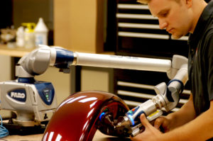
FIGURE 2.1 Portable CMM
Most traditional CMMs are large fixed machines (they stay put and are not easily moved). Relatively new on the scene are the portable variety. The two best known brands are FARO arms and Romer arms. You will hear those names used loosely to mean the whole class of portable measurement arms (due to good marketing from both companies). Both are very competitive with each other. They come in 6 axis or 7 axis variety and allow very free movement of the manually guided probe. This freedom of movement is extremely useful for getting into tight spaces. Their portability and many mounting options (clamp, vacuum, magnetic, tripod) make them versatile equipment that can go almost anywhere. We have service customers in 48 states and 7 countries at the moment. Everyone here is waiting for that Hawaii or Alaska job to show up to round out the 50 states (I will have to hold a raffle to see who gets to do those jobs). However, along with the freedom they provide comes lower general accuracy. The reason is due to the number of encoding devices required by each. These have between 6-7 glass encoders versus the 3 scales of a fixed CMM. Each of these adds a bit of error to the equation. There are also ways to make these devices able to capture measurement envelops of practically unlimited size. This is through a leap frog operation that allows movement of the unit between measurements. It does cause extra error in the measurements overall. However, larger objects tend to have larger tolerances to accommodate this.
The accuracy of CMMs range from millionths to low thousandths of an inch. The former are prohibitively expensive for most companies and the later are affordable but not cheap considering their base price, the price of maintenance and qualified staff. They are available in almost any size with the largest ones being generally less accurate but more expensive.
Laser Tracker/Laser Radar
![]()
FIGURE 3: Laser Tracker Head Without Tripod
Laser trackers have been around for a while and are used heavily in precisely aligning large equipment or for measuring large parts or parts separated by large distances. They are basically similar to giant manually operated point probes. They collect one point at a time using an SMR (Spherical Mounted Retroreflector). The SMR is hand held and the reflector always has to point at the tripod mounted base unit. There needs to be line of sight to the tripod mounted tracker from the SMR. There accuracy is very good and in the low thousandths of an inch generally speaking. If you can limit the use of the rotational encoder in the tracker (by moving the tracker far enough away from the object being measured that it does not have to turn through much of an angle), you obtain the most accurate results.
They do collect point clouds like a fixed CMM but must be human operated like a portable CMM (which they are also considered to be). There measurement range is up to 120 meters and the point density of the data is relatively low. Their accuracies are typically in the low thousandths of an inch. They can be combined with portable arm based CMMs to gain more flexibility and accuracy when line of sight restrictions come into play. There are various accessories that can replace or augment the SMR to allow for measurement of edges and other features. There are also probing options that allow incorporation of smaller hand held probes to capture data in hidden areas.
Nikon’s Laser Radar is the best upcoming challenger to this technology. This is technically a touchless data collection system. However, I am including it here as it is so close to laser trackers in function. Laser radar avoids the requirement of holding an SMR and is programmable. Nikon’s recent marketing efforts are geared toward automotive and inline inspection of vehicles. However, there are a myriad of uses for the technology. It also has a scanning mode that can generate a relatively large point cloud. The accuracies are very similar to laser trackers.
Summary
At 3D Engineering Solutions, we work to combine the best existing types of equipment to perform your scope of work. Sometimes the traditional and common measurement equipment is superior to the high end touchless data collection systems. Our goal is to provide you with the best information for your project in the most efficient and cost effective way. If you have upcoming inspection, reverse engineering or troubleshooting requirements, we would love to quote this for you. Please contact us at 513-771-7710.
Leave a Reply
Want to join the discussion?Feel free to contribute!