How is the Accuracy of Industrial CT Scans Verified?
Industrial CT scanning continues to gain popularity for use in measurements. The real question to be asked is: Is the data extracted from CT scans accurate? Since its inception, CT scanning has been used to visualize internal structures from people to industrial items. It is unparalleled in its ability to see those things that are hidden inside an assembly. It is also important for measuring the effects of an assembly in its assembled state. Using CT data to provide accurate measurements has always been around but there was no universally agreed upon ways to ensure the validity of the measurements.
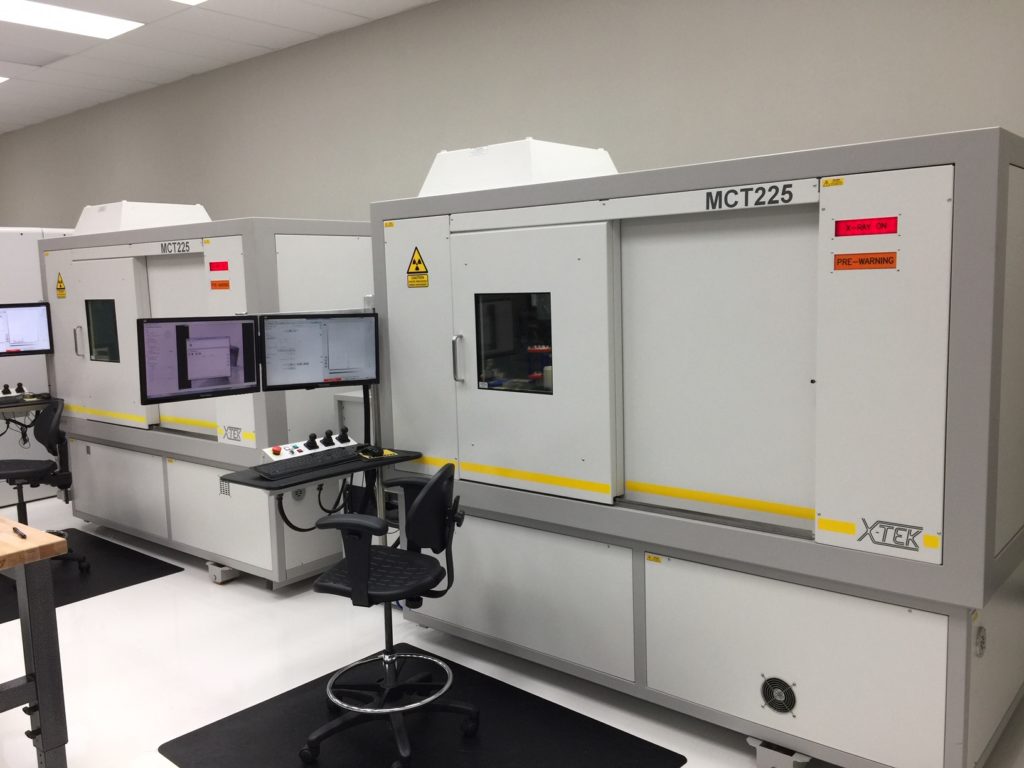
Several companies have addressed this issue in recent years. When we explored our first CT equipment, we only found 2 that advertised and sold a metrology grade industrial CT machine. That was Nikon and Zeiss. A couple of years ago, I re-looked at what was available and found a total of 5 industrial CT scanning OEMs who offered metrology grade CT. This indicates a definite trend in the direction of having equipment that has a better basis for measurement values.
We have been told that the European auto component manufactures sometimes specify that their products be now inspected with CT. I do not see this in the US auto market yet, but am starting to see this more in aerospace prints.
A majority of what needs to be well controlled by a metrology grade CT scanner is related to understanding the magnification. This is typically controlled by using linear scales (CMM scales) in order to get an accurate representation of where the object (which sits on a stage/manipulator) is relative to the x-ray source and the x-ray detector. The distance from the source to the detector is also controlled through laser calibration. Traditional visualization CT equipment does not accurately control these relative positions. So the image is still visually correct but can be dimensionally imprecise.
To get an idea why the source, object and detector distances are important, imagine that the x-ray source is a flashlight and the detector is a wall. If you put an object between the flashlight and the wall, it will cast a shadow. If you move that object closer to the flashlight, then the image on the wall will grow larger. This is the effect of magnification (X-rays are just photons). If we know where the object is in relation to the flashlight and wall, then we can know the size of the object.
The other items that metrology grade CT machines control are internal machine temperature and the stability of the equipment. Temperature affects the size of an object being measured and these machines can generate some heat – so it is best to control this. Also using a stable base for source, object and detector, will limit any unwanted motion and result in more precise results.
Just like CMMs need to be regularly calibrated, so do metrology grade CT machines. This is typically done with laser calibration. The position of the manipulator/stage is checked and adjusted throughout the range of the equipment (just like a fixed CMM). A calibration report is generated just like a standard CMM. All of this extra specialized equipment has a cost and metrology grade CT machines are much more expensive than the standard visualization based CT machines. This type of machine can be 30% more expensive than a standard CT machine and does require regular calibrations.
This is in stark contrast to traditional CT machines that are sometimes calibrated with a tape measure! Yes – a tape measure is sometimes used to check/calibrate the distance between the source and detector of some traditional machines. I could not believe it either when I heard it from a source that does this. If a machine is not regularly calibrated, you must use a different method to verify each scan.
All of the metrology grade CT machines advertise an MPE (Maximum Permissible Error) formula for their equipment. This helps in developing measurement uncertainties. And that information is needed to add a capability to an ISO17025. Currently there are no ISO specs for calibrating CT machines as exists for fixed CMMs (ISO 10360 series of specs) or portable CMMs (ISO 10360-12). However, I did notice one that is under development ISO 10360-11. In the absence of this, we use a waiver of traceability from our ISO17025 accreditation body. Additionally, we use our own internal testing and artifacts to help validate our results.
If you don’t have access to a metrology grade industrial CT machine, you have to seek alternate means to verify any dimensions taken from the data. This is typically done with an artifact calibrated by a traceable CMM. Two of our four CT machines fall into this category. They are new machines but not metrology grade machines. We use barbells of various materials (Ruby, steel or ceramic spheres with steel or carbon fiber tubes separating them). We scan them before, during or after we scan a part.
This is a decent method to verify scans if you take precautions. We take the data from our artifact and compare it to the CT scan with the artifact in it. If they are different, we scale the CT data to the artifact.
Using a pair of spheres is one of the best ways to scale a CT scan. The distance between 2 spheres is an easy and well known solution. It is a point to point distance which only has one interpretation (the shortest distance between 2 points). You do have to monitor the temperature of your scanning environment. The growth in the distance between the spheres can add error. This can be mitigated with lab controlled temperatures and good knowledge of the temperature changes inside the CT machine. We use HOBO temperature data loggers to monitor each of our lab spaces and use them for CT machine temperature studies.
Spheres also get past another issue that can be caused in CT scanning related to surface determination. The operator has some control over where the CT software says the surface is by controlling what method is used for surface determination. This could cause a sphere to be slightly larger or smaller in diameter. For our barbell type artifacts, this is not an issue as the center points do not change their relative distance from each other. We verify our scans by also looking at the diameter of the spheres and sometimes take direct dimensions from the parts we measure.
Most providers of CT service do none of this. Before we purchased our first machine we used different services and found scaling issues – even within the same lot of parts which were presumably scanned in the same machine using the same parameters. For visualization, this is not an issue but for metrology purposes, it leaves one without a basis for the measured values.
Regardless, all values collected from artifacts or the part itself are listed in our inspection reports under a method section. This allows our customers to see how we verified the measurements and what those results were. We also use these methods in our metrology grade CT machines if we suspect an issue.
One of our measurement artifacts is made from carbon fiber with ceramic precision measurement spheres. We use this for a ‘round Robin’ artifact that we check against a total of 18 instruments including our CT equipment. The benefit of using the same artifact is that we can cross check and validate our equipment calibration status and track this over time. This gives us a real time understanding on how each piece of equipment is performing and performs over time in between calibrations.
This leads to another point about using a service provider for CT scanning. You should always ask what type of equipment your scans are taken on. Look at it this way, when you receive an inspection report, it is common practice to have the specific machine, manufacturer and model indicated in the report. Why should industrial CT for metrology be any different? You might be surprised at what cobbled together equipment there exists that is passed off as high quality measurement grade equipment. Of course that equipment may be great for visualization and troubleshooting issues in products – but are not great for establishing a chain of traceability to assure your end customers.
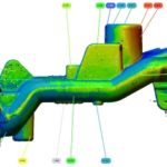
We have been able to successfully validate our CT results through our customer’s internal studies. A couple of them have sectioned their samples to verify the location and size of internal defects. This yielded a beautiful comparison and validation of the accuracy that we were able to achieve. That would make a great article, but unfortunately those reports are proprietary to our customers.
Contact us today at 3D Engineering Solutions to discuss metrology CT scanning and your requirements.

Leave a Reply
Want to join the discussion?Feel free to contribute!