Using Laser or Structured Light Scanning to Preserve Your Tuned Molds and Dies – Just Like Notre Dame
Your Molds and Dies are critical to your business. They were meticulously created and iteratively tuned until the parts they produce are within specification. At that point, they were put into production and no documentation of the final tuned geometry was captured. This is actually the standard operating procedure for most of the world. The problem occurs when a part gets stuck and the equipment is cycled again and the tool cracks! Now you are stuck with having to go through the entire tuning process again. Or are you? With laser scanning and structured light scanning you may be in luck.
Notre Dame Connection
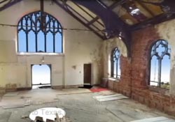
The world was shocked on April 15, 2019 when Notre Dame caught fire and damaged this historic church. As people we tend to take things for granted until they are damaged or gone. The church has stood since the 12th century. Why wouldn’t it stand forever? The same can be said for any of our historic buildings or artifacts. Fortunately, someone had a thorough long range laser scan of the entire church just a few years before. So if, they decide to rebuild to the same dimensions as before, they have an accurate as built record of this to go by. It is not for certain if they will try to rebuild to match what was there before or to creatively add a new touch. Either way they have the documentation needed as a starting point whichever way they go. Here is a link to a video on a historic Cincinnati Ohio landmark that we scanned that can be used for this purpose: Union Terminal Laser Scan. The image shown above is from some similar work done with a Small Church Laser Scan. It was being moved from Ohio to Texas. We captured this for a complete documentation of the structure before it was disassembled and moved.
The other critical item that this data is useful for is for comparison of the current damaged structure to the original laser scan. They could decide to take additional data of the structure in its current damaged state and then overlay that data to the undamaged state. This would quickly give them a ‘Scan to Scan’ comparison of before and after the fire. This comparison would visually highlight any areas that have moved that were not directly involved in the fire. Why would they want this? Well, the fire caused some obvious damage to the structure, but they would be wise to check to see if other adjacent structures are not also damaged. A scan to scan comparison would reveal if the adjacent structural members have moved because of the load shifts due to the fire. The apparently undamaged sections may have been carrying some of the load from the damaged area and may be in jeopardy of further damage now that part of the load that had been balanced so well for so long is no longer present.
How This Applies To Your Molds and Dies
The same things can be done for your damaged tools and dies or as an insurance policy for undamaged ones. If you were able to have a scan done just after the tool tuning was complete, you would then have a template to cut a new tool or component. This might still require an iteration or two but will get you very close to the original state of your tool. This could save weeks of tuning time for complicated tools.
The actual scanning activity is very quick an takes only hours. Services like 3D Engineering Solutions can even come on site to your shop and do the scanning. The idea would be to preserve a record of where the tool is at a time when it is producing known good parts. Later if something in the part dimensions changes or if the tool breaks, then you have a backup and a quick place to start.
Later you can use this as the basis for a wear analysis by rescanning the tool and comparing that data to the original data. Then you will be able to highlight the differences and wear that has occurred. Or rule out that the mold geometry has changed significantly if you are experiencing issues. This can also be a great way to show your end customer that your tooling has remained constant over various periods of time.
Help When Your Mold or Die Breaks
If the tool breaks, then you have a point cloud data set that can then be reverse engineered. This is, in fact, the majority of the reverse engineering projects that we do at 3D Engineering Solutions. We are experts in data collection and modeling and employ degreed engineers to do both.
However, if you don’t have data already captured from the tool while it was in good shape and that mold or die has now cracked or broken, we can still help. We can scan your broken tools and digitally fix them and present you with a CAD model that can be cut to that shape and save you time. While this works well, it is always better to have data from the undamaged tool. Sometimes the obviously damaged areas of the tool have affected or distorted other areas of the tool (similar to my Notre Dame description above) and we would not know that that is the case. Usually these effects are small. However, if you have complex or tightly toleranced tools that may make a difference.
Please contact us today to discuss how we can provide you with scan data, reports or CAD models to help protect your critical tool and die investments.

Leave a Reply
Want to join the discussion?Feel free to contribute!